


How to create a cable modem config file
Cable modems get their operational parameters using config files. These config files define what the internet subscription will be, what additional services are activated and other configuration details. This blog post will get you started creating your own modem config file.
What’s a config file
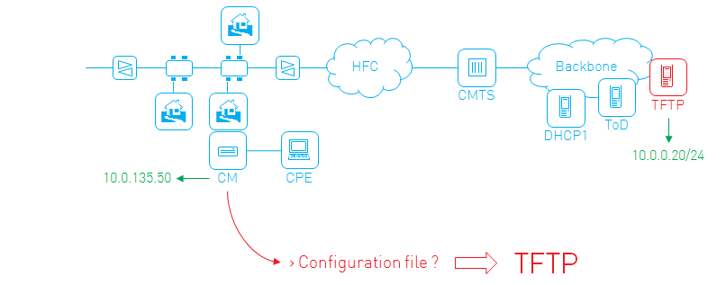
The config file is sent to the cable modem as part of the provisioning process at boot time, using the TFTP protocol.
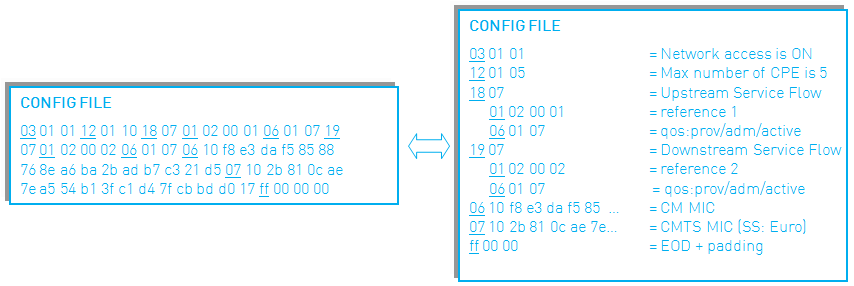
It’s a binary file consisting of different TLV (type-length-value) encodings. The value of a TLV can again be a TLV, thus creating a tree-like structure of TLVs and sub TLVs.
The essentials
At the very least, these TLVs need to be present:
- Network Access Control: enabling or disabling network access for the customer using the cable modem
- Upstream Service Flow: describing how packets will be sent upstream (from the modem into the network)
- Downstream Service Flow: describing how packets will be sent downstream (from the network to the modem)
Example:
Network Access Control:on
Upstream Service Flow Encodings
  Service Flow Reference:1
  Quality of Service Parameter Set:provisioned admitted active
Downstream Service Flow Encodings
  Service Flow Reference:2
  Quality of Service Parameter Set:provisioned admitted active
There, you’re done. You’ve just created a working config file! Note that this is the config file you start with when launching the DOCSIS config file editor. Two other necessary TLVs, CM and CMTS MIC are added automatically by the editor.
Adding a speed profile
All done? Well… there are a few shortcomings to this config file. It grants unlimited internet speed, to name but one.
So we need additional sub TLVs to refine the service flows. To create a 160/10 Mbps downstream/upstream internet subscription for example, you can use the following service flow configuration:
Upstream Service Flow Encodings
  Service Flow Reference:1
  Quality of Service Parameter Set:provisioned admitted active
  Upstream Maximum Sustained Traffic Rate:10000000
  Maximum Traffic Burst:10654
Downstream Service Flow Encodings
  Service Flow Reference:2
  Quality of Service Parameter Set:provisioned admitted active
  Downstream Maximum Sustained Traffic Rate:160000000
  Maximum Traffic Burst:10654
The Maximum Sustained Traffic Rate limits the speed, while the Maximum Traffic Burst setting allows tweaking the observed latency. You can read the gory details, including a lot of other service flow encodings in the MULPI spec, Annex C.
Adding additional services
With our internet service completed, it’s time to add other services.
For a voice service e.g. the signaling packets (used to set up a call) need a higher priority than the internet packets. The actual voice packets will use a dynamically created service flow, so we don’t need to worry about those in our config file.
Let’s create the additional service flows (note the unique reference numbers):
Upstream Service Flow Encodings
  Service Flow Reference:3
  Quality of Service Parameter Set:provisioned admitted active
  Traffic Priority:7
Downstream Service Flow Encodings
  Service Flow Reference:4
  Quality of Service Parameter Set:provisioned admitted active
  Traffic Priority:7
Traffic Priority ranges from 0 to 7 (higher is more priority). Therefore these service flows will get priority over the internet service flows (with a default priority of 0).
Adding a classifier
To make sure that the voice signaling packets will use those newly defined service flows, and not the internet service flows, we add classifiers that map or “classify” a certain packet to a certain service flow, e.g. for an NCS-based VoIP service:
Upstream Packet Classification Encoding
  Classifier Reference:1
  Service Flow Reference:3
  IP Packet Classification Encodings
    IP Protocol:17
    TCP/UDP Source Port Start:2427
    TCP/UDP Source Port End:2427
    TCP/UDP Destination Port Start:2427
    TCP/UDP Destination Port End:2427
Downstream Packet Classification Encoding
  Classifier Reference:2
  Service Flow Reference:4
  IP Packet Classification Encodings
    IP Protocol:17
    TCP/UDP Source Port Start:2427
    TCP/UDP Source Port End:2427
    TCP/UDP Destination Port Start:2427
    TCP/UDP Destination Port End:2427
The modem will now classify upstream UDP packets originating from and destined to port 2427 on the service flow with reference 3, which is our high-priority service flow. Likewise, the CMTS will classify the downstream voice signaling packets on service flow with reference number 4.
All packets that are not matched by a classifier are put on the primary service flow, this is the first service flow that is encountered in the config file.
Adding SNMP access
A lot of operators are still using SNMPv2 as the main protocol to remotely manage the modems. A number of TLVs are available for easy configuration of this SNMP coexistence:
SNMPv1v2c Coexistence Configuration
  SNMPv1v2c Community Name:private
  SNMPv1v2c Transport Address Access
    SNMPv1v2c Transport Address:10.10.10.0/0
    SNMPv1v2c Transport Address Mask:255.255.255.0/0
  SNMPv1v2c Access View Type:read-write
  SNMPv1v2c Access View Name:docsisManagerView
These settings will allow SNMP v1/v2 read-write access from a management station within the 10.10.10.0/24 subnet to all the MIBs in the docsisManagerView (defined in the OSS spec, basically everything) using community string private.
What’s next?
Glueing the pieces from the previous paragraphs together, you’ve created an SNMPv2 manageable cable modem with a 160/10 internet subscription and high-priority voice signaling.
Other services (like e.g. eRouter or L2VPN) or configuration options (like filters, software upgrade parameters or vendor specific settings) can simply be added to this config file. Annex C of the MULPI spec gives a full overview of the possible TLVs in a config file.