Extended upstream power allows 3.0 cable modems to transmit upstream bursts at higher powers than previously established. This feature has been added some time after the introduction of EuroDOCSIS 3.0. But why? Do we need higher powers now than before?
Noise is everywhere
To operate at its maximum capacity, the RF-network needs to be in optimal shape. When you take a look at the nuts and bolts of the physical network layer and signal propagation, sooner or later you are confronted with noise. Noise is always present and makes data transmission harder than you wish it to be.
Noise imposes limits in terms of modulation. To start, this blog post delves into the details of this and shows that bit errors are more likely to occur because of noise and higher modulation orders. It can cause packet loss but also modem flaps, which is the technical term for modems that momentarily lose connection, go offline and then come back online again. In the end, we want the best signal quality and increasing the upstream transmit burst power is the possibility we will look into in this blog post.
Let’s gather some background information first.
All roads lead to SNR
In this story, all roads don’t lead to Rome, they lead to the Signal-to-Noise Ratio (SNR) instead. To fully understand what it is, first know that it is an aptly named parameter. The SNR is the ratio of signal power to noise power.


or rather in decibels:


An upstream signal transmitted by a CM will be demodulated by the CMTS upon arrival and the SNR plays a significant role in the succes of this process. Noise can only be reduced partially by factors that are under your control, like component selection, quality installations and mitigation techniques. Other factors are not controllable, think about
- degradation of connections and material quality over time
- variable in-home interference
- weather influences
When in doubt, send harder
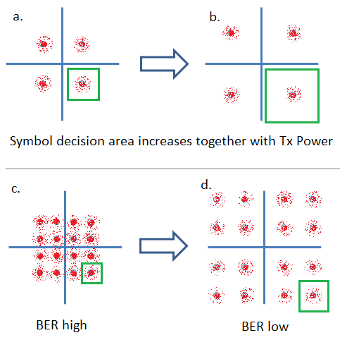
Consider modulated signals by taking a look at the constellation diagram. We know that higher modulation orders have more constellation points that are all closer to each other. Noise causes each constellation point to become a patch. Worst case, this patch grows beyond the bounds of the intended symbol. This will lead to demodulation errors and subsequent bit errors.
The image below shows the effect of an increase in transmit power and what the benefits are for higher modulation orders.


The noise is constant in all four scenarios, only the transmit power is variable. Situation (a) shows a QPSK modulated signal at low powers. The constellation points do not overlap, and thus an increase in power as depicted in scenario (b) is not required or beneficial.
Things are different in scenario (c) however, where the QAM16 signal has its constellation points so close that the noise causes the patches to overlap. Increase the power to scenario (d) to see that the larger distance between the points avoids the overlap.
We now have the technical information needed. This paves the way for a little bit of history.
An unexpected fallback
One of the biggest technological advances of EuroDOCSIS 3.0 has been the deployment of channel bonding. However, this created some worries when considering upstream power levels. The figure below shows a timeline with actions and consequences that occured with the introduction of EuroDOCSIS 3.0.


Before EuroDOCSIS3.0 there was no channel bonding. When using a single QPSK channel for upstream transmission, a cable modem could send out at a maximum power of 58dBmV. With the advent of EuroDOCSIS 3.0, transmitting on two or four such channels simultaneously causes the total power to go up by 3 or 6 dB respectively. An important characteristic of a signal transmitter is the amount of noise generated by the transmitter itself. It is a given that as the transmitted power increases, so does the self-generated noise. The consequence is that in the initial version of the EuroDOCSIS 3.0 specification it was decided to lower the maximum power with 3 dB per channel.
Note that with 3 dB power less per channel, four bonded channels have a total power that is 3dB higher than a single channel. We understand that lowering the transmit power lowers the SNR and have also established that the SNR should be high to support high modulation orders. We now find ourselves in a situation where this modulation cannot be used because the signal power per channel has been limited. So, when using newer technology, the capacity is limited rather than increased!
Extended power
In 2010, four years after the initial specification, ECN MULPIv3.0-N-10.0943-5 Extended Upstream Power was released. Its introduction was driven by operators that wanted to deploy high modulation orders to satisfy growing bandwidth demands. The term extended upstream power was coined to allow modems to transmit at higher powers, even exceeding those established for single channels. From an operators perspective, it is the easiest way to gain SNR.
So where are we now?
Extended upstream power allows modems to send at powers up to 61 dBmV per channel. Currently, early in 2015, modems do not yet support these highest levels, it is common to find support up to 54 dBmV. It is a challenge to build a transmitter that can send multiple carriers at the highest power level without generating too much noise of its own.


Conclusion
Present and future bandwidth demands will consolidate the use of high modulation orders. In order to get the cable modem to communicate reliably to the CMTS, it should adhere to an important rule: “Can you speak loud AND clear into the microphone please?”
More information
If you found this post interesting, you might also be interested in the Introduction to HFC Networks training course, where noise sources and mitigation techniques are discussed. Modulation techniques (and constellation diagrams like the one above) are explained in Introduction to Data Communication Systems. To learn more about (Euro)DOCSIS 3.0 features, consider the Overview of EuroDOCSIS 3.0, M-CMTS and BSOD or In depth EuroDOCSIS 3.0 training courses.


