Will my cable modem survive 3 V/m, 5 V/m or 10 V/m?
From time to time operators or manufacturers ask us to verify how well a CM can cope with LTE interference.
Will a cable modem / cable gateway suffer from a nearby wireless (LTE800) signal? How well can it withstand such a wireless signal? This post will dive into the wonderful world of (LTE) interference testing on cable modems.
Will it survive 3 V/m, 5 V/m or 10 V/m?
The proof of the pudding is in the eating. Let’s find out!
More specifically we are going to observe what happens when a modem is online (e.g bonding 4 channels) and ‘gets hit’ by some in-band interference signal.
This means that the (wireless) signal is using the same frequency as the (wired, coaxial) modem [1].
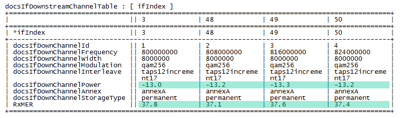
As displayed below, my modem is online using 4 channels (800 MHz .. 824 MHz) and is receiving these QAM 256 DVB-C/AnnexA channels at a low receive level of approx. -13.0 dBmV.
The device is online and is reporting 37.8 dB of signal-to-noise ratio.
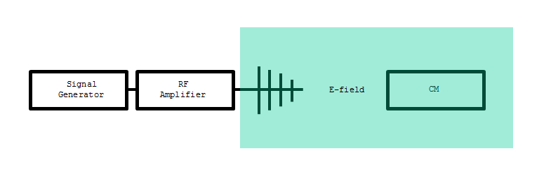
Now let’s bring in the signal generator, a power amplifier and an antenna to shoot some signal at the CM.
(Do not try this at home, you prefer to do this type of tests in an anechoic chamber…)
You will need to spend some time calibrating the setup, but eventually you can generate a calibrated E-field which you can throw onto the CM.
Tune the LTE signal to that same 800 MHz and crank up the power.
Eventually the downstream channel (with the same frequency as the LTE signal) will start to deteriorate.
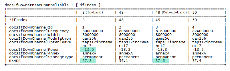
In the table below, we hardly have a working channel at 800 MHz.
At -13 dBmV the signal-to-noise reported (as parameter RxMER) is 27.8 dB which is considered to be a serious degradation. Note that channel 49 (which is out-of-band) still has 37.6 dB. At 27.8 dB MER a channel is barely usable, the forward error correction tries to correct receiver errors but cannot correct all of them, as a consequence packets will get lost.
If this channel is the primary EuroDOCSIS downstream channel then the CM is close to going offline. If this is a non-primary channel then it will end up in partial-service mode.
Repeating this same exercise at different receive levels results in a plot like the one below. For each selected receive level (in the typical cable receive level range -13 dBmV .. 17 dBmV) the E-field corresponding to a signal-to-noise ratio of 27.0 dB is plotted.
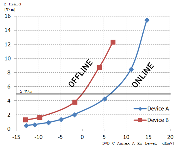
The red line is the result of the same exercise, but this time executed on another device (Device B).
This device has higher shielding against the LTE signal. Depending on the combination receive level/interferer strength you end up above (offline) or below (online) the curve.
Example: Consider Device B (red line) online at 0 dBmV. If you increase the E-field you will observe a reduction in MER reading due to the interfering E-field. When you reach 5 V/m the MER reading will be 27 dB. Going higher than this level, and as such crossing the red line, will result in downstream demodulation failure. The CM will go offline (assuming the channel is the primary downstream channel).
How would all these parameters relate to each other?
Would it be possible to express the level of shielding against an interfering signal as a single number?
It turns out that an in-band shielding factor can be calculated quite well using the CM reported values.
The table below shows various sample points taken during this exercise together with intermediate calculation values.
The value which represents the System Shielding Efficiency (SSE) is calculated by combining parameters which can be fetched from the CM and the strength of the E-field.
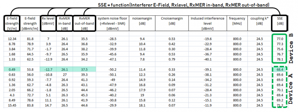
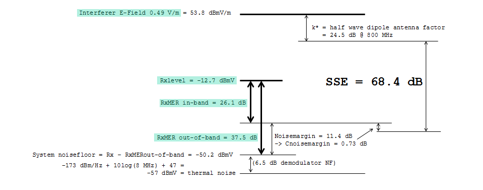
If you like to understand more on the calculations, check [2], which walks through the different aspects of wireless interference on cable. The picture provided in [5] shows the relation between the parameters.
So, 3 V/m, 5 V/m or 10 V/m?
As we have seen, the answer depends on the SSE (which is essentially determined by the hardware) and the operational parameters of the CM.
Assume your device has a measured SSE of 90 dB, and is online at -13 dBmV 256 QAM (worst case scenario).
For 5 V/m this results in a calculated 27 dB MER (which is not error free, packet errors…). The channel would really be killed by 10 V/m and 3 V/m gives a calculated MER of just under 30 dB (occasional errors, but correctable) [3].
Real error free operation is officially [4] expected at 34.5 dB. For a 90 dB SSE this results in error free operation at an E-field of 1.5 V/m.
LTE800 Immunity Certification
From experience we know that a CM can pass the LTE800 Immunity Certification (at 5 V/m) from SSE values of 94 dB (at all possible orientations). At least this is what it takes to survive the in-band interference test.
Other functionality tests might still give issues.
E.g. Wi-Fi or telephony fails when an out-of-band LTE signal is present …
Footnotes
[1] We also assume that the interferer signal is occupying less bandwidth than our 8 MHz wide downstream signal, so that all energy from the wireless signal is striking in the DVB-C band.
[2] http://www.anga.de/media/file/518.Addendum_Report159_CableNetworkProtection.pdf
[3] If you are familiar with V/m and dB’s, to your surprise, you might spot that taking half of the voltage does not result in a change of 6 dB. The reason for this is that at -13 dBmV – 34.5 dB = -47.5 dBmV/8MHz you are working close to the receiver (or network) noise floor. In the calculations this is accounted for in the Cnoisemargin factor.
[4] CM-SP-PHYv3.0-I12-150305, B.6.3.3 CM BER Performance
[5] Without going through the detailed mathematics (which are described in [2]), the picture below shows the relations between the parameters. It might make things a little more understandable.
More information
Excentis offers a standalone LTE Immunity certification test program. The objective of this program is to ensure that cable services are not disturbed by electromagnetic fields generated by wireless equipment (currently LTE devices) using the 790-862 MHz sub-band of the digital dividend frequencies.
A submitted product (CM, EMTA or STB) can be submitted for LTE Immunity certification against a specific level of E-field. By default this is 5 V/m, but a submitting vendor can alternatively request for the product to be tested with a different E-field. Allowed E-field values are 3, 4, 5, 6, 7, 8, 9 or 10 V/m.
This gives full flexibility to the vendor so that it can build its products against the specific immunity requirements of its customer(s).