Take care of your cable network health
Nothing is perfect. We all know this, and we have to live with it. However, trying to improve is a key to success. This is true for cable networks as well. A bad plant condition and interferers may degrade the communication between CM and CMTS. Luckily though there is lot of data that can be monitored to detect quite some issues.
This blog post aims to provide a better understanding of the available information and how this can be used in a monitoring system. As you might know, information on a CMTS can be fetched via three interfaces; SNMP, CLI and IPDR. For now we will only focus on SNMP (using MIBs).
The MIBs that will be discussed can be divided into two domains. MIBs with more or less clear limits, and MIBs that must be interpreted according to their context.
MIBs with known limits
Following table shows a view on the most typical EuroDOCSIS 3.0 requirements (for US-DOCSIS and pre-3.0 other limits and MIBs apply). In a healthy network following conditions will be met:
- values are not too close to the limits
- values are stable over time
- small difference between values over different channels
| Power | SNR | Microreflections | |
| CM Tx | Max 55dBmV (QPSK)(*) Max 52dBmV (QAM16)(*) Max 51dBmV (QAM64)(*) (*) 4 upstreams |
transmit equalization ON: =35dB for all modulations > QPSK |
|
| CM Rx | -17/+13dBmV (QAM64) -13/+17dBmV (QAM256) |
=25.5dB (QAM64) =34.5dB (QAM256, -13 to -6dBmV) =31.5dB (QAM256, -6 to 17dBmV) |
-10dBc@<=0.5µs -15dBc@<=1µs -20dBc@<=1.5µs -31,5dBc@>1.5µs |
| CMTS Rx | Configured Rx point +/- CMTS threshold e.g. 0dBmV +/- 6dB |
target values: =13dB(qpsk) =19dB(qam16) =25dB(qam64) |
-10dBc@<=0.5µs -20dBc@<=1µs -31,5dBc@>1µs |
Record the Power
It’s important to keep all powers at the cable modem (CM) as well as CMTS side within their limits, preferably with a certain margin. The CM docsIf3CmStatusUsTxPower MIB represents the operational transmit power per upstream channel. At the CMTS, the docsIf3CmtsCmUsStatusRxPower MIB can be used to obtain the receive power per CM and per upstream channel. Both downstream transmit and receive power can be monitored with the docsIfDownChannelPower MIB, depending if you query the CM or CMTS.
Observe the SNR
SNR (signal-to-noise ratio) is also a very important parameter. It compares the level of a desired signal to the level of background noise and is expressed in decibels (dB). At the CM, the docsIfSigQSignalNoise MIB will give you an idea of the SNR of the downstream channel as received by the CM. At the CMTS, the docsIf3CmtsCmUsStatusSignalNoise can be used to read the SNR per upstream channel per CM. Alternatively, you can also use the docsIf3SignalQualityExtRxMER or docsIf3CmtsSignalQualityExtCNIR MIB. The first one provides an in-channel MER (modulation error ratio) measurement while the second one provides an in-channel carrier-to-noise plus interference ratio. It’s especially ingress noise that is reflected in SNR. To see the impact of impulse noise it is sensible to check the FEC values as well.
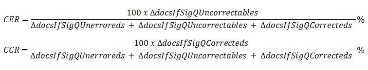
Calculate CER/CCR
Forward Error Correction (FEC) is a technique used to detect and correct transmission failures that happen at the physical transmission layer. This is a powerful feature increasing the reliability on noisy channels and preventing that packets are dropped. The best way to use these values is calculating the CER (Codeword Error Rate) and CCR (Corrected Codeword Rate) over time.
For example, downstream CER and CCR:
CER/CCR can be calculated both in upstream and downstream direction. The MIBs from the docsIfSignalQualityTable can be used for the downstream CER/CCR on the CM (as in the formulas above), the MIBs from the docsIf3CmtsCmUsStatusTable can be used for the upstream CER/CCR on the CMTS per modem per upstream channel.
High values for CER will indicate packetloss which means service degradation. An increment of CCR is alarming.
Values for upstream CER can for example be divided into four categories:
- 0.5%: real time service degradation
- 1%: normal data service degradation
- =1.10-3: acceptable
- =5.10-4: ideal
For the downstream the CM must achieve a CER of less than or equal to 9.10-7.
Scan for Microreflections
Microreflection (docsIfSigQMicroreflections) and equalization data (docsIfSigQEqualizationData) is also helpful data provided by the CM. These reflections are caused by impedance mis-match and might result in packet loss. The data can be used to estimate the presence, location and severity of reflections. On the CMTS similar MIBs are available: docsIf3CmtsCmUsStatusMicroreflections and docsIf3CmtsCmUsStatusEqData.
MIBs requiring interpretation
Some MIBs are used to detect or investigate issues but do not have clear requirements. However, when properly interpreted they can deliver additional value to your monitoring system. Often these will show a correlation with the MIBs with known limits just discussed.
Detect Partial Service
When a bonded CM has lost one ore more channels we call this Partial Service. It’s obvious that this can result in performance issues. This is however difficult to monitor as there is no “Partial Service MIB” that can be used to determine if a CM is operating in Partial Service. There are however other possibilities to detect whether channels are disconnected. For example the docsIf3CmStatusUsRangingStatus MIB can be used to denote the ranging state of the CM per upstream. When a 3.0 CM has no usable upstream channels anymore it will re-initialize. As a result of this reset the docsIfCmStatusResets MIB will be incremented. The docsIfDownstreamChannelTable MIB can be used to check if there are disconnected downstream channels.
Listen to timeouts
Monitoring the ranging timers of a CM might also be very useful for troubleshooting as it indicates whether there were any CM-CMTS communication failures. Two important MIBs that can be used are the docsIf3CmStatusUsT3Timeouts MIB (wait for ranging response) and the docsIf3CmStatusUsT4Timeouts MIB (wait for unicast ranging opportunity).
More information about these timers can be found in a previous blog post (Ranging – Feeling the 2 bpm DOCSIS heartbeat) where the essentials of ranging and its pitfalls are described.
Perform spectrum measurements
For RF related problems like signal interference you might want to perform spectrum measurements. For the CM this can be done by configuring and reading the MIBs in docsIf3CmSpectrumAnalysisCtrlCmd and docsIf3CmSpectrumAnalysisMeasTable . For the CMTS you need the docsIf3CmtsSpectrumAnalysisMeasTable.
Discover the event text and diagnostic log
The Event Text is very convenient because this contains human-readable information of events and problems of CM and CMTS. These logs can be found in the docsDevEvTable MIBs.
On the CMTS the Diagnostic Log can provide extra information. This is a tool where you can predefine conditions to detect ranging and registration problems with CMs. For example: A CM is added to the log as soon as two RNG-REQ (ranging request) attempts are missed out of ten. To achieve this you need to configure the docsDiagLogTable.
Conclusion
As you can see there’s a lot of information that can be collected. It’s a true challenge to store all the data, correlate the values and monitor changes over time. Afterwards the next step might be alarming and trending. Once that’s achieved you’ve built a nice monitoring system.
The recommendations in this article are very useful for (Euro)DOCSIS 3.0, but in 3.1 a whole new toolset will be available: PNM (Proactive Network Maintenance). PNM gathers lots of data from close to the PHY layer in order to determine and locate negative factors as soon and quickly as possible. Quite interesting toolbox that allows a network operator to detect issues before the customer notices them. We plan to take a closer look in a future blog post.


Hello Stefaan,
My question is about the threshold for partial downstream service.
below what CER should the CM send a status message to the CMTS , requesting to enter partial service, and in which document has this been defined ?
Best regards
Paul van Schagen
Hi Paul,
Good question! The answer is however not that straightforward.
The CM will only send a CM-STATUS message when it lost a downstream when it is configured to do so by the MDD CM-STATUS Event Enable Bitmask (configured by CMTS CLI). There are two events that can trigger the CM to send the CM-STATUS that it lost a SC-QAM downstream, those are “MDD timeout” and “QAM/FEC lock failure”. There is no CER trigger defined in the DOCSIS specifications, it only states the term “unusable” which is considered to be modem vendor specific determination.
Experience showed however that modems seem to implement a CER trigger, for example having x uncorrectable codewords within 10 seconds might trigger a FEC lock failed.
So unfortunately no threshold is defined, the behaviour will be vendor dependant. It is for sure useful to test whether the implementation is according to your wishes.
Best regards,
Bart
thanks Bart for your reply ,
excuses for late reply , I just saw it a few days ago.